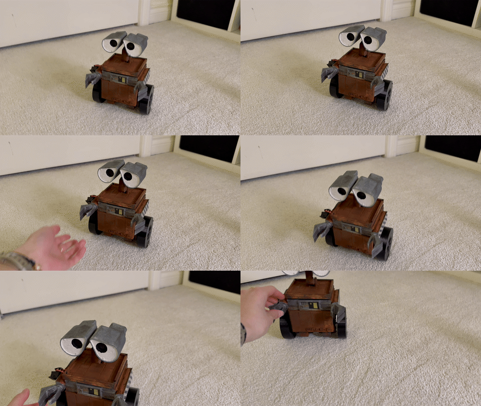
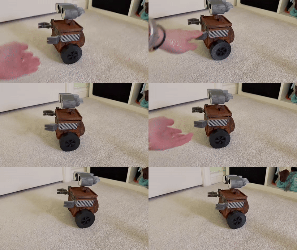
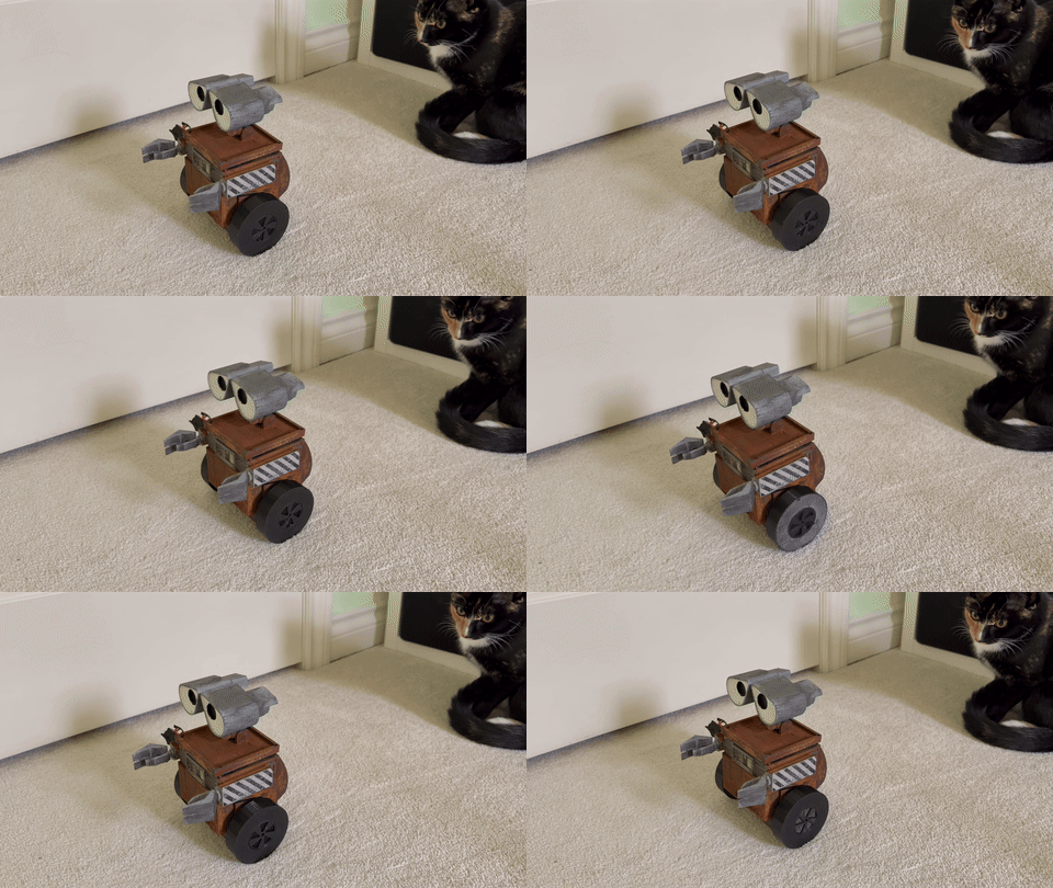
WALL-E Robot
This article describes my process for creating a dual-wheel self-balancing robot. The CAD and code for this project can be found here.
I wanted to go through the process of creating/tuning an inverted pendulum, but wanted to have some fun with it. Also, I lowkey don’t have enough space to make an inverted pendulum.
Goals
Become familiar with a new motor (steppers) since I’ve only really used servos and DC motors
Understand more of the controls behind inverted pendulum
Preamble
Component selection
Using stepper motors NEMA17 for wheels.
Chose steppers due to high precision in comparison to DC motors, and high speed compared to servos. Probably could’ve used some special servo that fits needs but stepper seems generally better
Considerations: generate higher heat and draw more current
Amazon link $19 per motor, 1.5A, 12V specification
To use stepper motors it is also necessary to have a suitable stepper motor driver. I used the A4988 board because it is cheap and the current specs match the motor I chose.
I basically exclusively use LiPo batteries in my projects because they have a built-in BMS so I don’t have to worry about it.
Using an arduino for ease. Other good option would be to use an esp32 which would add some complexity
The main IMUs used in hobby projects are the MPU6050 and BNO055. I chose to use the BNO055 because it is more accurate and less prone to drift.
Print body and head in PLA, no big decision basically just the default option
Print wheels in TPU 95A (easily available), want to have the more grip/traction than PLA
Decision making
NOT making the head movable. This is because it adds complexity that isn’t desired according to the goals. No goal was to make it show emotion/be entertaining. Would love to do that sometime but not for this project
Same with arms, arms will be static
Basically, making it look like WALL-e purely because I enjoy making my projects look nice, this robot will not mimic walle in its behaviour or use
Progress
Design
An inverted pendulum is a mechanism with the center of mass (CoM) above its pivot point. The most important thing to consider during the design process for such a system is the distance between the CoM and the pivot point. Torque is formulated as
where tau is torque, r is radius (distance from pivot to point of force) and F is the force applied perpendicular to r. In the inverted pendulum, the force is applied at the CoM. This means that torque is proportional to the distance to the CoM, thus the farther the CoM is from the wheels, the more torque is needed from the motors to counter the force. However, another element related to torque is the moment of inertia. This is described by
where I is the moment of inertia, omega is the angular velocity, and t is time.. Rearranging in terms of t gives
Moment of intertia of a rod about one end is defined as
Where M is mass, and L is length. Relating length to time, time is proportional to the square of length, meaning a higher length corresponds to more time to counter the force. This explanation may have been a bit convoluted, but consider balancing a pencil on a finger. The longer the pencil is, the easier it is to balance since you have more time to move under the pencil’s CoM, whereas when its shorter you have less time to react. This fundamental idea is crucial to the inverted pendulum mechanism. Even though it takes more torque to overcome perturbations when the CoM is farther, the motors must react much faster making it much harder to stay balanced. It is ideal to have the CoM as far from the pivot point as possible.
Looking at the CAD, you will notice I did not really follow that principle. This was because I prioritized aesthetics over functionality in this case, and I thought it would be interesting to see if its still tunable with this lower CoM.
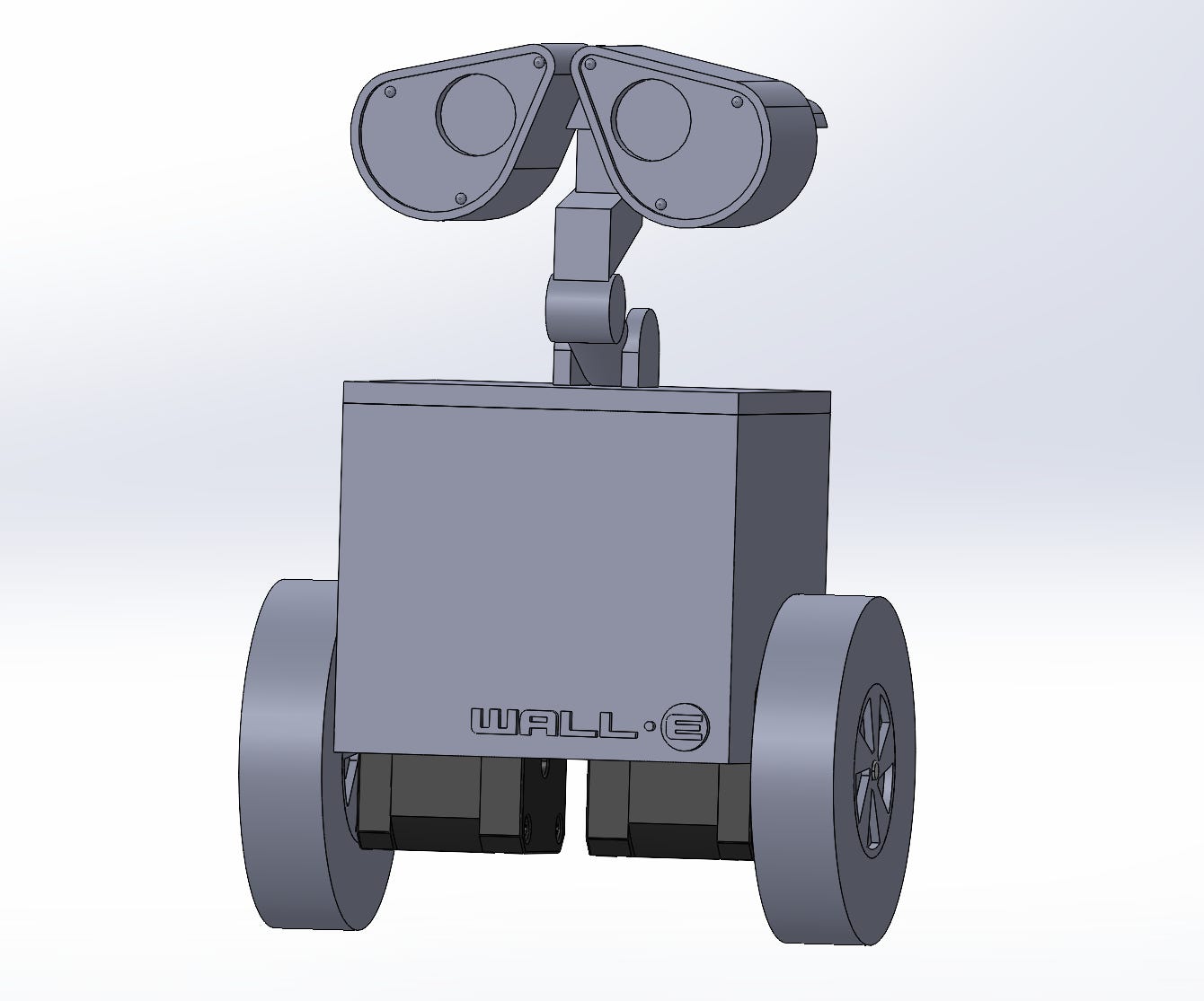
The initial CAD is just a box on wheels. After adding things for aethetics, it looks more like this:
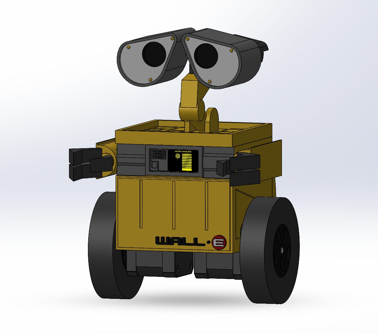
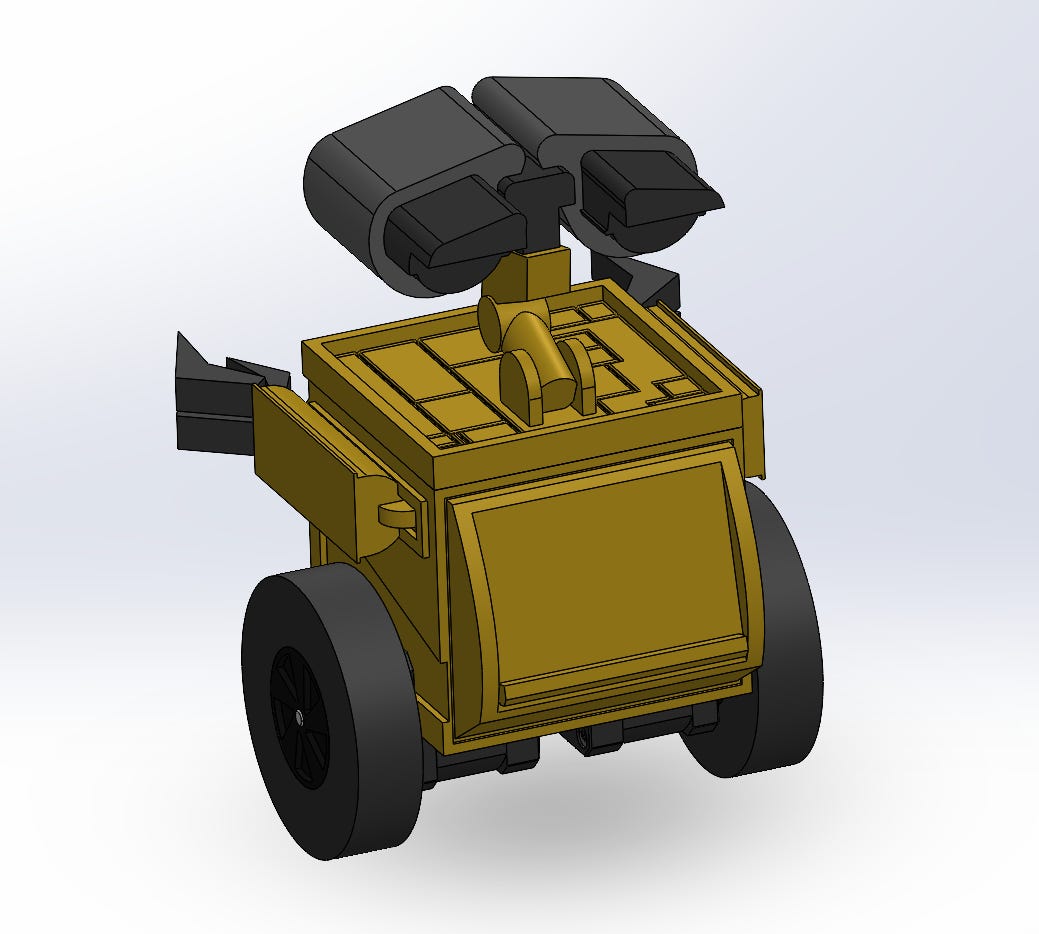
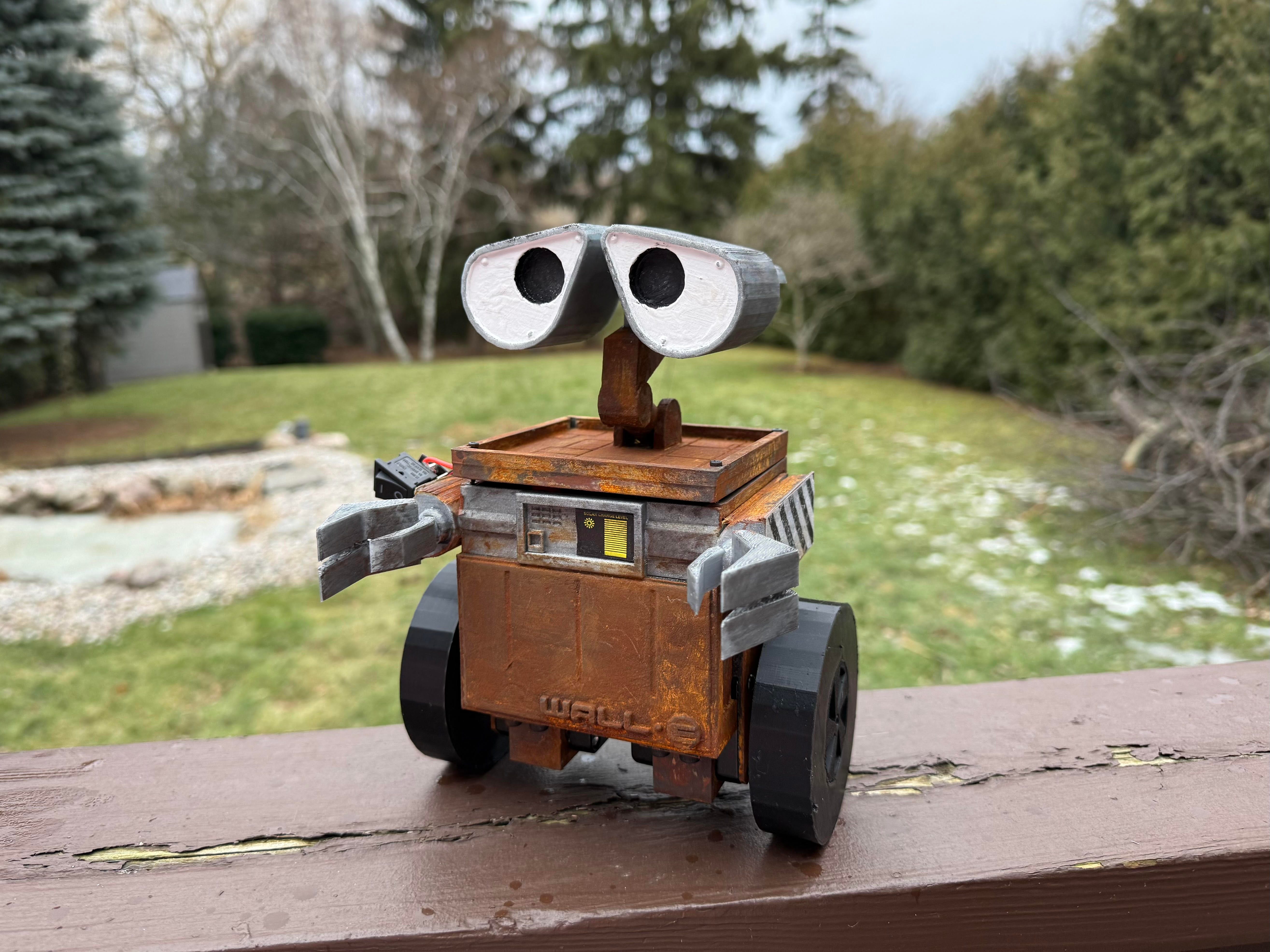
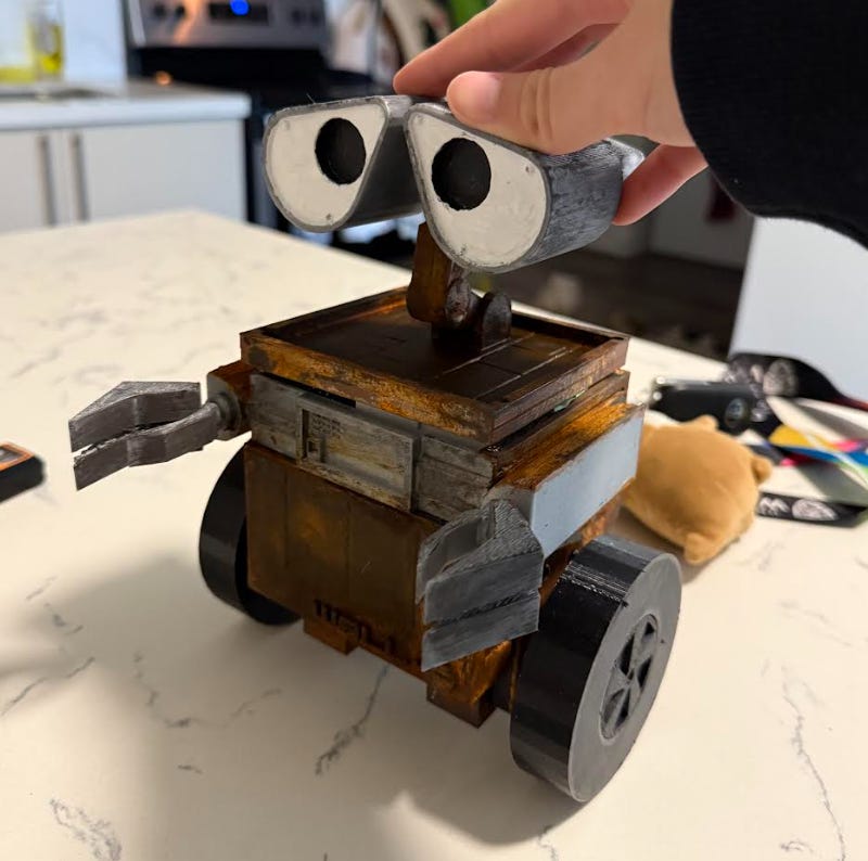
When printed, painted, and put together, it looks like this:
Wiring
I found this guide very helpful for figuring out how to use stepper motors. For power distribution, my original idea was to use a 12V battery running to the motors and using a buck converter to step down to 5V for the arduino, but all the 12V LiPo batteries I found were at least 1100mAh and way too heavy and frankly overkill. Instead, I found that using two separate batteries was lighter. I used an 11.1V 500mAh battery for the motors, and a separate 7.4V battery with a buck step down to 5V for the arduino.
Through following the guide, my connections looked like this (sorry no schematic lol):
Right motor:
A4988 DIR -> UNO D2
A4988 STEP -> UNO D3
Short A4988 sleep and reset
A4988 VDD -> UNO 5V
GND -> GND
Find stepper pairs by seeing which pairs have resistance, any 2 will be A1 B1 and other 2 will be A2 B2
Left motor:
A4988 DIR -> UNO D4
A4988 STEP -> UNO D5
Short A4988 sleep and reset
A4988 VDD -> UNO 5V
GND -> GND
Find stepper pairs by seeing which pairs have resistance, any 2 will be A1 B1 and other 2 will be A2 B2
IMU
BNO055 Vin -> UNO 5V
GND -> GND
BNO055 SCL -> UNO A5
BNO055 SDA -> UNO A4
Program
The goal of the code is to keep the angle at a particular setpoint. It uses the motors to accomplish this. If the IMU is tilting a certain direction, the motors should move in that direction to move back under the CoM. There are three big pieces in the code to execute this:
IMU senses the tilt angle
Controller decides how to drive motors (PID)
Write the output to the motors
As a system this looks like
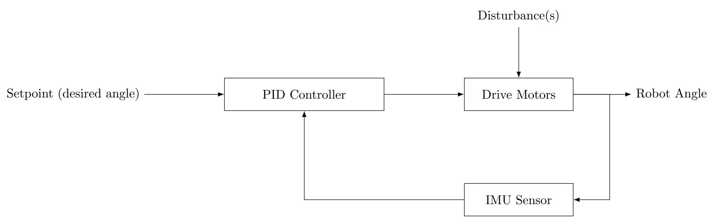
The code can be found here.
Tune PIDs
I tuned the proportional gain until the robot was able to balance. When the p gain is too low, it is unable to react fast enough to balance. If it is too high, it oscillates aggressively at the setpoint.
Once it is able to balance, some differential gain was added until it oscillates the least, while still balancing.
I ended up not adding any integral gain because it wasn’t needed, and because I gain is kind of finicky. Didn’t seem necessary to add it just for the sake of it.